The Zhongtang Bridge on xx highway has a main span of 32.5 + 4 × 45 + 32.5m and equal section prestressed reinforced concrete continuous box girder (post-tensioning method), with a total length of 245.9m. The box girder is a single room, beam height at the center is 308.25cm, roof width is 1100cm (width of the bridge deck is 12m),and bottom plate width is 480cm. The web is inclined, and the middle distance at the top plate is 570cm. The beam ends and the middle of the whole beam are provided with beams, and the rest are provided with diaphragms every 15m.
The pier foundation of the main bridge is 4 bored cast-in-place piles with a diameter of 120cm, which are embedded in the bedrock for more than 50cm. The pier body adopts a double-column structure of reinforced concrete with a diameter of 180cm.
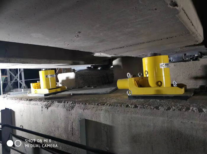
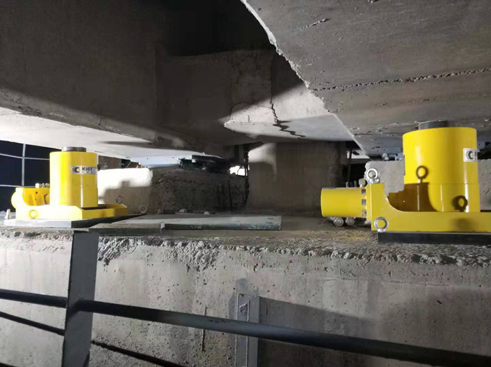
When the bridge is erected, SSY method is applied, that is, multi-point pushing method is used to erect the beam. The characteristics of this method are: the horizontal reaction force when pushing (pulling) the beam body is dispersed and acting on each pier, and the pushing (pulling) operation can be controlled centrally. Since there are no temporary piers during work, the front end of the box girder is connected to a 30m-long fabricated steel truss as a guide beam.
When the prefabricated box girder is pushed up, it is carried out in a cycle according to the procedures of advancing→lifting beam→dropping beam→propulsion. Figure 1 shows the case of a cycle.
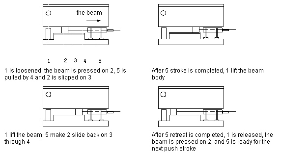
Diagram of the push-up procedure
1——Vertical Cylinder;2——Drag Head;3——Slideway;4——Pulling Rod;5——Horizontal Cylinder
It can be seen that to realize this program cycle, the horizontal cylinder completes the action of pushing the box girder through the sliding device, and the vertical cylinder completes the action of lifting and dropping the beam. That is, the horizontal cylinder and the vertical cylinder are alternately acted.
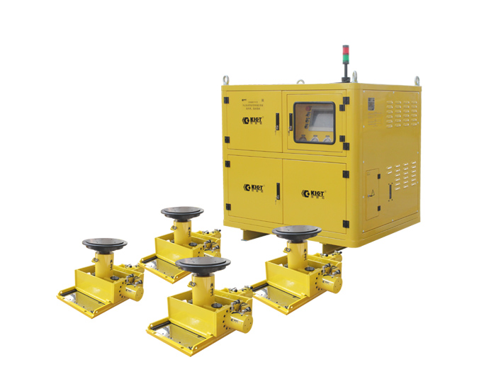
1. Hydraulic system of multi-point pusher beam and its control
Both of the horizontal cylinder and the vertical cylinder are hydraulically driven and controlled by electricity. The total length of the box girder to be pushed for the bridge is 225m, and each linear meter weighs 16.8t, with a total weight of about 3770t. Therefore, a total of 10 horizontal cylinders and 24 vertical cylinders (the oil pressure is 320kg/cm2 and the output is 250t) are arranged. There are 5 piers with horizontal cylinders, 2 for each pier; there are 6 piers for vertical cylinders, 4 for each pier.
The vertical jack completes the lifting and lowering of the beam. In the construction process, the whole bridge is not required to be synchronized, and the piers are required to be divided, so there is no problem of centralized control. Its electrical control can complete the continuous lifting or lowering of the jack, and can also complete the jog form.
The horizontal jack completes the beam pushing action. The construction process requires the whole bridge to be synchronous, that is, to output or stop at the same time, so the centralized control of the horizontal jack is set up, and a centralized control electrical box is set up for this purpose.
The use of horizontal jacks and vertical jacks is gradually increasing, and the box girder is prefabricated 15m per cycle. With the continuous growth of the box girder, the number of jacks used gradually increases. In the last few cycles of prefabrication, all of the 10 sets horizontal jacks and 24 vertical jacks are used.
In order to connect each pier with the centralized control room, we installed an intercom sound transmission system. Practice has proved that the hydraulic transmission system and control methods listed above are reliable to use.
Let’s talk about some experiences of several problems of the hydraulic transmission of the push frame beam method for reference.
1. The problem of graded pressure regulation of the hydraulic system. The problem of step-by-step pressure regulation is put forward due to the different consideration of static friction resistance and dynamic friction resistance when the box girder moves. In the past, it was always believed that the hydraulic system should have two or three oil pressures: when the static friction resistance is overcome, a larger oil pressure is used; and a smaller oil pressure is used when the box beam slides. The method is to change the hydraulic system by connecting the different relief valves that have been set. In this way, the hydraulic system and its control are slightly more complicated. Our practice has proved that the oil pressure of the hydraulic system does not depend on itself, but on the external resistance of the jack. That is to say, when the hydraulic system is working, its oil pressure is not determined by the quantity on the nameplate of the oil pump, but by the total resistance encountered during the flow of the oil back to the oil tank after leaving the pump. If the jack has no resistance (load), the pressure of the oil pump is only determined by the resistance of the pipeline; if the oil from the oil pump immediately enters the atmosphere or the oil tank, the pressure of the oil pump will be zero; if the resistance (load) R of the jack increases, the pressure of the oil pump also increased. When the jack is unloaded, the pressure of the oil pump is determined by the one-way valve; when the jack is loaded, the pressure of the oil pump, that is, the oil pressure of the system, will be determined by the resistance of the jack. The oil pressure at work is determined by the jack load. That is to say, the oil pressure of the hydraulic system will change itself with the external resistance, so the step-by-step pressure regulation is unnecessary.
2. Sync issue of horizontal jacks. The pushing process requires that the left and right horizontal jacks should push the beam forward at the same speed, otherwise the beam will be deflected when it slips. Of course, the first thing people consider is that the force applied by the left and right horizontal jacks to the beam body should be equal, which is correct. When the left and right symmetry of the beam body is excellent, and the resistance is equal to the left and right, of course, the force applied by the left and right horizontal jacks should also be equal. The second consideration is that the left and right forward speeds should also be equal. In this way, the beam can run smoothly and straight. However, it is difficult for the beam body to ensure that each section must be perfectly symmetrical on the left and right, and the resistance on the left and right must be equal. The oil pressure related to the system mentioned above is determined by external resistance. It can be imagined that the left and right jacks must work under different oil pressure conditions, so will the speed of the left and right jacks be synchronized at this time? For the sake of illustration, it is assumed that only one pair of jacks of one pier is working. Since we set one pump with one jack, this solves the problem of speed synchronization very well. Because the oil pump we use is a quantitative positive displacement pump, in theory, no matter how much resistance the oil output by the oil pump encounters (that is, no matter how high the oil pressure of the system is), its flow rate is unchanged. Therefore, the left and right jacks must be synchronized. Of course, this conclusion can also be inferred to the situation of two piers with four tops, three piers with six tops, four piers with eight tops, or five piers with ten tops. Therefore, our method of one pump and one top can better realize the problem of left and right synchronization. Practice has also proved that in the push beam, the center line of the box beam is basically not offset (strictly speaking, it should be slightly offset from left to right but it can always be kept within a certain range). The construction process requires close monitoring of the deviation of the center line. If it exceeds 2cm, it needs to be corrected (with lateral guidance). During the push-up process, the number of corrections is very small. Only one or two times in thirty pushes (a 15m box girder). This can be considered as the combined result of many objective factors, because as far as hydraulic machinery is concerned, the oil pump has a flow error, the jack has internal leakage problems (each jack is different, and the piston may be in different positions), and the system Leakage of other devices inside, etc., which is not contradictory to our conclusion above.
3. Sync issue of vertical jacks. Our vertical jacks work by a pump with four jacks, and a synchronizing valve should be set up, because the synchronizing valve (or diverter valve) can make several jacks under different loads (resistance) still obtain a predetermined ratio or equal oil supply to achieve synchronization. But considering that a synchronizing valve has only two outlets. In order to simplify the structure of the system, no synchronization valve is installed. Considering that the left and right weights of the box girder are symmetrical, it is not a big problem to do so. Practice has proved that the estimate is correct, the vertical jack basically rises and falls synchronously, and there is no problem in the lifting and falling of the beam.
Post time: May-16-2022